 Cassandra.org
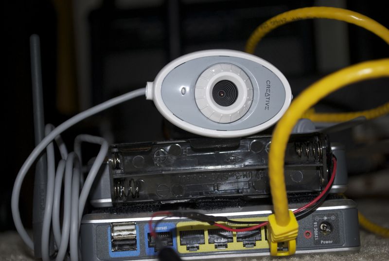
Sparky's Brains and Eye
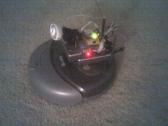
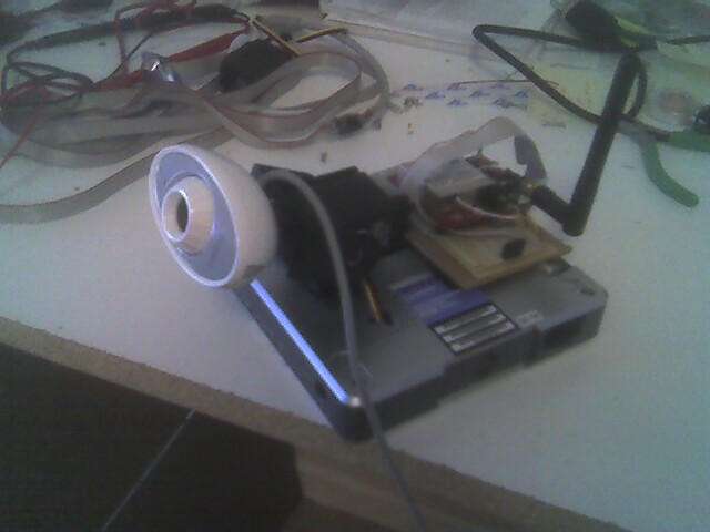
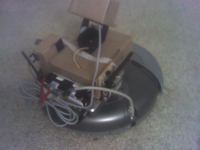
Sparky on the Move
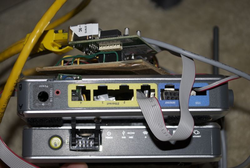
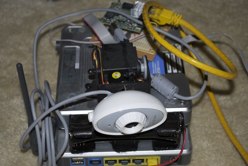
Sparky's Controller (rear view)
Story
I'd been living in a carpeted apartment for over 2 years and did not
own a vacuum, nor had I ever vacuumed the place. A seemingly unrelated
fact is that I had previously been involved in some academic robotics
projects and liked tinkering with hardware.
Where these two things come together is the Roomba vacuum
(manufactured by iRobot), which is both a platform for domestic work
and robotics projects. I bought one (Discovery SE model) and I named
him Sparky (after a suggestion from a co-worker) because you absolutely
need to start early with the anthropomorphic stuff when working with
robots. The Roomba provided actuators (motors and wheels) and sensors
(infrared and bump sensors) and a not so clever, but heuristically
effective vacuuming algorithm in its firmware. It also also had all
the interfaces (hardware and software) for connecting your own
controller and writing your own software algorithms that used the
actuators and sensors. By the time I bought one, there was a well
established knowledge based on all the ways one could augment the
Roomba.
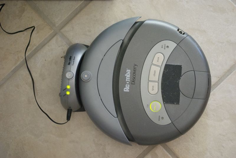
Sparky in 2011
(with remnant velcro)
(with remnant velcro)
A major goal I had as I embarked down the path of experimenting with
the Roomba was to not permanently change it in any way. It had to be
designed so that at any moment, all additional hardware could be
removed, and it could function for its manufactured purpose of
vacuuming. There was a whole lot of false starts, lots of electronics
and tool purchases, some fried hardware here and there, plus lots of
experimentation and revisions along the way. However, this main goal
was most successfully fulfilled, and it serves as a vacuum to this day
(circa Aug. 2011) which is four years after I started and a long way
from when I last used it as a robotic hacking platform. The only
visible indication of its past life as an experimental platform is a
patch of velcro on the top where the "brain" would be mounted.
Final Roomba Setup (unmounted)
The end result was an on-board "brain" capable of implementing control
algorithms, an on-board camera and servos for taking pictures/video and
manipulating the camera's pan-tilt head. It also had a wireless
Ethernet connection which could send and receive data. This additional
hardware required auxiliary power in the form of an on-board battery
pack of 8 re-chargeable AA batteries. It was capable of being fully
autonomous for as long as the batteries lasted. For testing, it could
also be tethered to a AC/DC wall wort power supply and it could take
commands through either a wired or wireless network interface.
Most all the time I spent was in building the hardware platform, trying
different pieces and getting everything to work together so as to have
a fully autonomous robot. Besides some simple proof of concept
algorithms that used the main on-board sensors and actuators, nothing
more sophisticated ever made its way into Sparky's brain. I was in the
process of making it recognize and follow people using facial
recognition. I got the facial recognition software so that the
pan-tilt camera head would follow your face as you moved. It was not
terribly robust to tilting of your head, but when it worked, it was a
little bit creepy to see this reacting to your movements in a "seeing
eye" type behavior. I was leveraging some off-the-shelf algorithms
from a math library, and try as I did many, many ways, I could not get
this software to run directly on Sparky's on-board hardware. All the
algorithm development was done on my laptop, and I needed to
cross-compile it for the hardware that was Sparky's brain. Each time I
loaded it into the brain, it would give errors and die and I never
figured out a solution for this. Here's where the project stalled out:
      Program received signal SIGSEGV, Segmentation fault.
      0x00510cb8 in CvType::~CvType ()
      (gdb) bt
      #0  0x00510cb8 in CvType::~CvType ()
      #1  0x00411010 in __do_global_dtors_aux ()
      #2  0x0055e3e4 in _fini ()
With this obstacle, other things in life eventually got in the way.
The project was shelved and that is as far as I ever got. All the
hardware is still in tact, and in theory it should still work as far as
I got years ago, but it just sits in a box now. So Sparky is now just a
simple domestic robot, without the higher-level functions needed to
become self-aware and turn on its master, which of course is what
happens with robots in the limit.
Project Details
I am writing this 4 years after I did this project and though I have a
slew of notes about what I did, it would take me a lot of time to
reconstruct the many, many things that went on in detail. So what
follows it just an outline of the highlights. If you really care about
all the gorey details (you probably don't), here are my detailed notes:
I started this project in late August of 2007 in my apartment in
Boulder shortly after having spent 6 months living in an apartment in
NYC and working way too hard for the last 2.5 years.
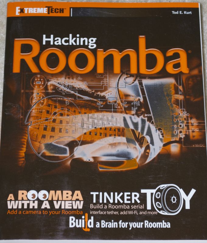
"Hacking Roomba" Book Cover
I bought a book on Hacking the Roomba for reference. Most of the
information was on-line, but the book was a good crutch to have and
helped find things more easily. It was a great way to get an
introduction to the Roomba.
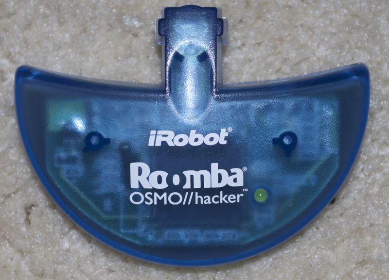
Module for Upgrading Roomba Firmware
First thing I found is that my Roomba model (Discovery SE) was
almost hackable. This version had all the hardware and
design of the next generation Roombas which were made easier to hack,
but the firmware was a couple months before they they fully worked
everything out. The nice part of this was that it only required you
to re-flash the firmware, and they had a nice little premade module for
doing this. The bad part was that they charged you about $29 for this
new firmware.
The Roomba has a DIN 7-pin connector which is annoyingly
almost the same as a PS/2 connector (previously common in
computer keyboards and mice). The difference of 1 pin meant you have
to lok harder to find the connector. My first task was to get
familiar with getting information from the Roomba and issuing commands
to the Roomba. This would be done directly from my laptop to the
Roomba to ensure I could actually control the thing. For simplicity, I
used some premade hardware from SparkFun Electronics, who were
conveniently located in Boulder where I was.
WiFi to Serial WiPort
SparkFun Electronics make a USB to Roomba cable (called the
"RooStick") and a wireless Bluetooth to Roomba transmitter and
receiver (called "RooTooth"). I started with the wired connection to
eliminate a variable for errors. The Bluetooth version was more of a
headache than it was worth.
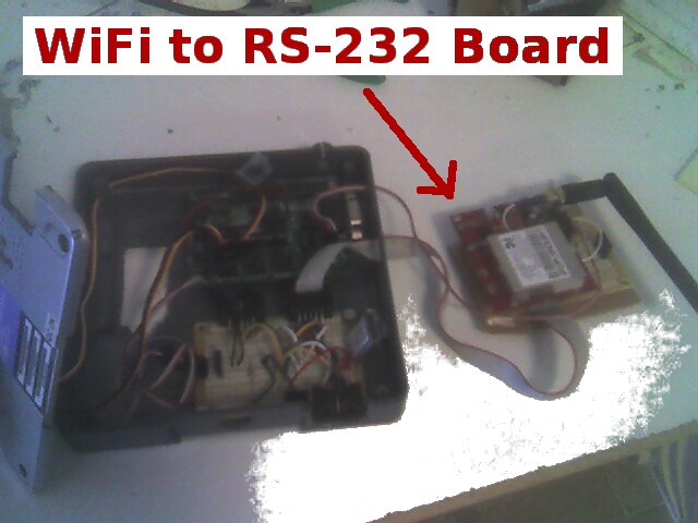
These devices became obsolete when I found a product that interfaced a
regular TCP/IP network to a serial device. Despite the funky cable,
the Roomba's control protocol was a simple, standard RS-232. Better
yet, there was a wired and wireless version. So I could put the
WiFi-to-serial board on Sparky, connect the serial outputs to the
cable going into sparky, and I could wirelessly control the Roomba
from my laptop: brilliant. Note that this is not the final solution,
since the end-goal was to make control happen on-board, but for
testing and debugging purposes, being able to control the roomba from
the laptop was invaluable.
I wound up doing a bunch of soldering and making a special board for
the WiFi-to-Serial board. I did not wan to solder that board directly
to the cable going into the Roomba, because this was just a tempoary
setup. So I made a board that would allow me flexibility to plug in
and out various ways to connect to the Roomba.
With laptop-to-roomba control, I downloaded a modified a bunch of
libraries and programs for the Roomba that would allow basic control
and information. This could be done through the command line or
through some simple PHP interfaces I made.
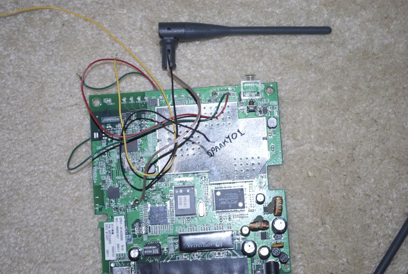
Inner Guts of Linksys WRTSL54GS
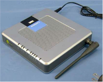
Linksys WRTSL54GS Router
The "brains" of Sparky would be a Linksys WRTSL54GS wireless router,
because this was effectively a mini-computer, complete with decent
amount of RAM, flashable RAM, USB port, GNU/Linux and was fully
supported for adding your own custom firmware. I bought two of these
since I knoew I would be doing hardware modifications and wanted to
have a backup for testing and in case something went wrong.
First step here was to reflash the firmware with a full (but compact)
version of GNU/Linux. The Linksys WRT54G class of routers is a
heavily hacked platform and there are tons and tons of resources out
there on this, including prebuilt firmware images. There was actually
too much outr there as I had to choose between two different
development branches: "kamikaze" or "whiterussian". There was much
back-and-forth here, especially as I got deeper into this and required
more customizations. For the this initial step, just learning how to
take apre-built image, flash the firmware, then log-on and configure
it was the main goal. Trickiest part at the start was to get all the
needed usb modules for the USB camera that would be used as Sparky's
"eyes".
First View from Sparky's Camera
Sparky's "Eye"
Once the camera was recognized by the router, I copied a bunch of
utility programs to the router that would allow it to dump images.
This was all proof of concept of getting the router and camera to work
and being bale to get images off the router.
Because the camera was USB and because I planned to add extra memory
via a USB memory stick, I bought a mini USB hub that I was going to
use on-board Sparky. The router came with only one USB port
(exposed). I ran into issues where the camera just would not work if
hooked up to the hub (and it was a powered hub). The solution was to
add another USB port to the rouiter. The board inside the router
supported two USB ports, but it just had nothing connected to the
second set of pins. I bought a USB connector and soldered it on to
give me two USB ports on the router.
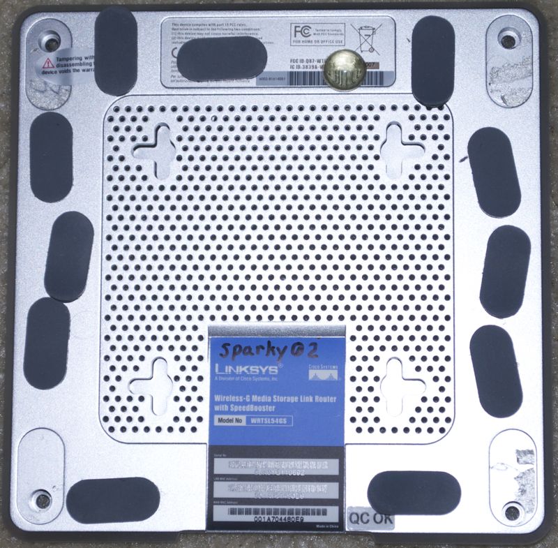
Cover of Sparky 02 (Linksys WRTSL54GS)
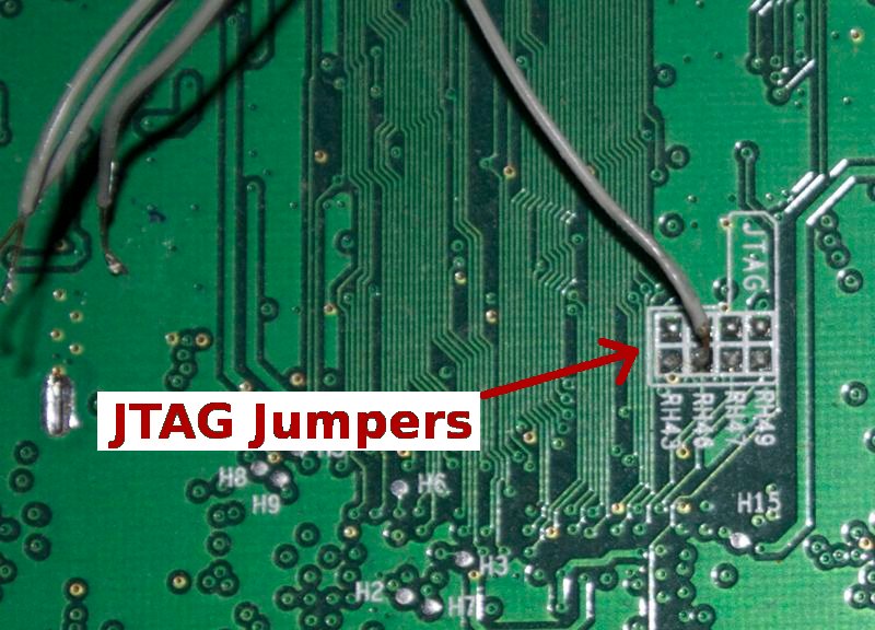
Debricking via JTAG Jumpers
At this point I was building custom firmware, trying to get everything
I needed and nothing I did not need. This required geting the source,
comnfiguring the builds, compiling and re-flashing the firmware.
There were many cycles of this as I refined the image, but at one
iteration, the flashing did not take. I had "bricked" the router (as
they say). I did not think there was anything significant between
this version and the other version, so attributed the problem to a
hiccup of some sort, so I unwisely thought I'd just use the backup
router. Now I had two bricked routers.
There was a whole slew of voodoo techniques for de-bricking these
routers. I tried them all, with the last ditch and most primordial
one being to make a special cable with specific resistors on each
wire, and soldered into the special "JTAG" jumpers on the board. With
special cable attached to the parallel port of the laptop and rigged
to the router, you run some magic incantation (software) and hope for
the best. No luck. I had no way of validating that I had even
constructured the cable the right way, so this was a real shot in the
dark. I gave up the fight and bought a third router.
Camera, Servos and Wireless Module
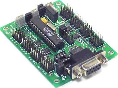
SSC-32 Servo Controller Board
Having a fixed camera on Sparky would be quite limiting. It would
require turing the robot to point the camera and it would not be able
to lopok up or down. The solution was to use a pan-tilt head using
acouple of servo motors. I found this very nice little servo
controller board (SSC-32) that was simple to setup and use and very
functional. This also was controlled via a serial interface, and
since I already had all the serial interface stuff worked out, fit
perfectly.
We now had the following hardware we needed to support:
- WiFi-to-Serial module : testing only from laptop
- Network-to-serial module : how router will talk serial devices
- Servo controller board : for pan-tilt head and status LEDs
- Battery pack : for limited stand-alone power
- Ac/DC tranformer wall-wort : for unlimited, but tethered power
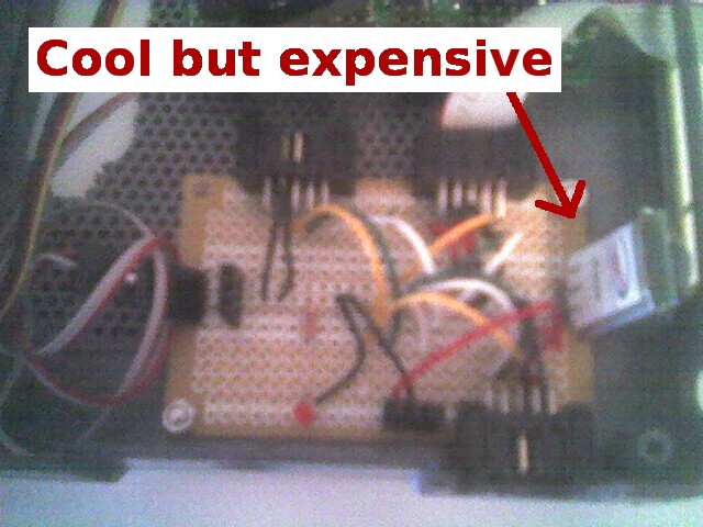
Power Distribution Board
(final)
(final)
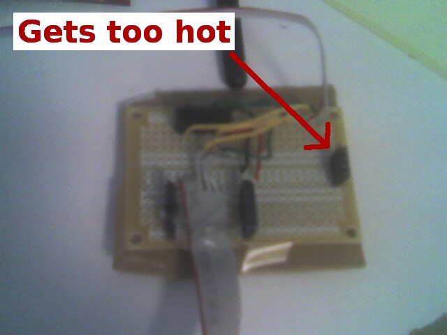
Power Distribution Board
(rev. 1)
(rev. 1)
A further complication was that there were voltage mismatches among a
number of these, so we needed some electronics to step up or down the
voltage as needed.
I wound up making a power (and serial line) distribution board that
would allow battery or wall-wort to plug in, convert to the right
voltages, and distribute the power and serial control lines to female
connectors mounted on the board. I could then neatly plug in and out
the compoents as needed. The first version of the power distribution
board used a brain-dead (but cheap) power step-down component that got
super hot and consumed gobs of power. I had to splurge about $20
extra for a smarter component.
Servo and Camera Testing
(cardboard enclosures)
(cardboard enclosures)
At this point, it was late October of 2007 and I got the third router
delivered. I went through all the setup needed for that. Despite
what you see in some of the pictures up to this point, I had no clean
solution for mounting all this extra hardware. For testing, I used a
few cardboard boxes and tape to hold it together. I was testing the
untethered use of the camera, pan-tilt head and streaming video from
the camera now.
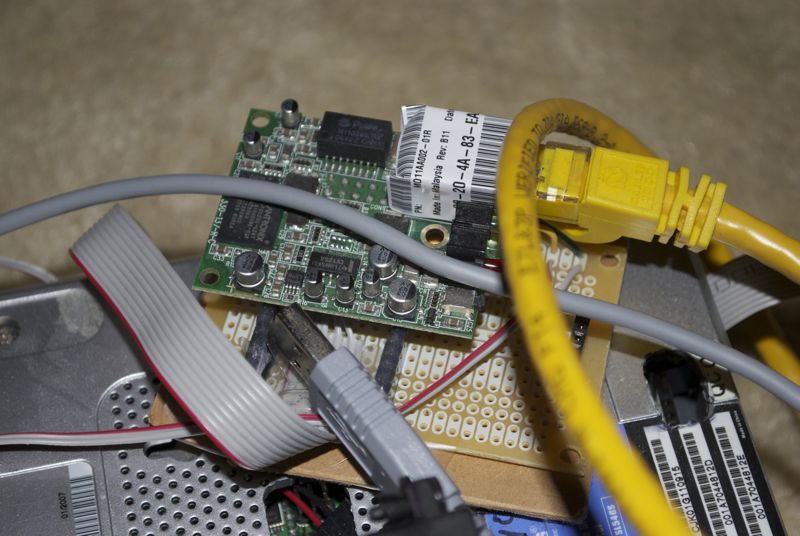
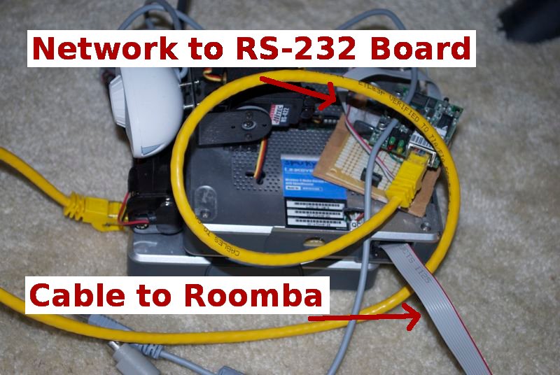
Ethernet to RS-232 Module

Rear View of Sparky's Brain
At some point, I had actually added a serial port to the Linksys
router. The pins where there on the board, but they were not
connected. I soldered them up wqith wires running to to a 10-pin
connector, and cut-away the casing to support it (see at
right). What I cannot remember is why I did this. I had a solution
where the router could control the serial devices threough a regular
network. Myabe I added it before I figured that out, or maybe there
were plans to eventually have a more direct serial control over the
Roomba or pan-tilt servos?
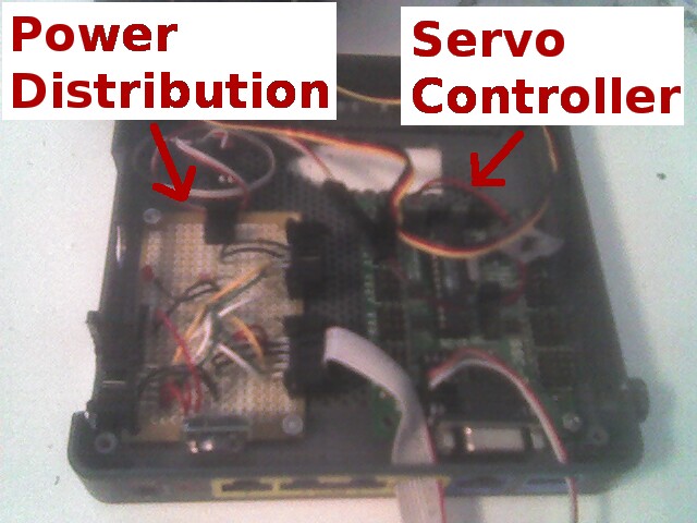
Power Distribution Module and Servo Controller
Side View of Sparky's Brain
I now had most of the hardware and interfacing issues worked out, so
it was now time to think about a neater solution to putting this
hardware on Sparky. I oportunistically used the enclosure from one of
the bricked routers, which housed the power distribution and servos
controller boards nicely (after a bit of dremel tool work on it). I
mounted the camera (and servos) to this, and stacked it on top of the
non-gutted router for a relatively nice look.
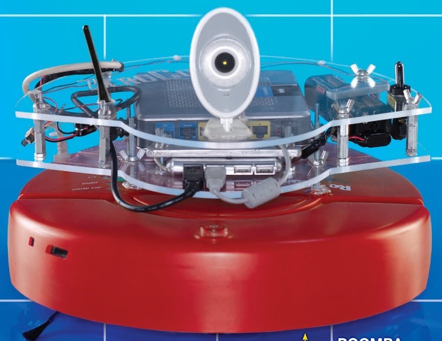
Make Magazine's Roomba
I thought my enclosures were not so bad and that it was a pretty neat
looking system (though too many cables showed). However, I very, very
recently (July 2011) opened up my new issue of Make magazine and saw
that they had an entire cover article on doing exactly what I did.
Their final product is pictured at right, which is certainly a much
nicer packaging effort. You can see this in their Volume 27 issue.
Their project is eerily similar to mine, down to the exact same
camera, battery enclosure and use of the WRTSL54GS router. It was the
appearance of this issue that actually prompted me to sit down and
write up what I did for my project pages. Note that they do not have
a pan-tilt head for the camera, which I think is way cooler to have
than some fancy clear plastic mounting plates.
One big limitation of the Roomba as a robotics platform is the
power/weight issue. With full compliment of bateries, router and
misc. boiards, this adds a non-trivial amount of weight to the roomba.
Besides your having to make sure it is balanced, it puts more downward
force than it was designed for. With a full charge on the roomba
battery and the auxiliary battery pack, Sparky could operate for a
little less than an hour, but this was with a minor load. More
batteries would be more weight, anf there is a definitel limit on the
weight.
With all the hardware built, it was time to do something more
interesting with the Sparky, which meant it was time to get down to
developing algorithms and writing software. I had the idea of making
Sparky my personal sentry robot, but before arming him with any sort
of lethal capabilities, I figured I better be able to make him
understand how to interact with people.
First task was to set up a development environment where I could
develop and test code on my laptop, with it remotely controlling the
robot, then cross-compiling it to load into Sparky brasin (the
router). I did the obligatory helloworld.c program, then a simple
hellosparky.c program that did some random sequence of wheel and
camera movements in response to the bump sensors. Lacking a video camera
at the time, there's no nice visual stuff to provide to show you from
this phase of the project.
A prerequisite to more interesting control, we to be able to get data
off the camera and process the pixels so that I could write programs
that reacted to what was happening on the camera. I had to adapt the
source code from the tools that were used to dump images from the
camera, and wrote a proof of concept program that would just insert a
green rectangle into the image. This completed the camera functions I
needd:: read image from camera, iterate over pixels, modify image, and
save to permenant storage.
The next level of sophistication I tried was to do facial recognition
and have the pan-tilt heads move to track faces. I found a facial
recognition software called "opencv" which I spent a fair amount of
time paring down, and also tinkered with some facial recognition
library from CMU. On the laptop, with the camera and pan-tilt head
hooked up directly, I was able to get this face tracking working. A
little eerie in a way, though the facial recognition library was not
very robust to roatation of your head. Still, the main proof of
concept of having the camera servos moving in regard to the live image
the camera was seeing was accomplished.
Trying to compile this for the router and run it on Sparky resulted in
a segmentation fault. I then tried all sorts of variations of
libraries, complile-time options, removing unneeded dependencies, but
each time continued ot get the segfault. Nothing worked, and that was
where the project ended (unless I decide to pick it up again at some
point,m which is unlikely.)
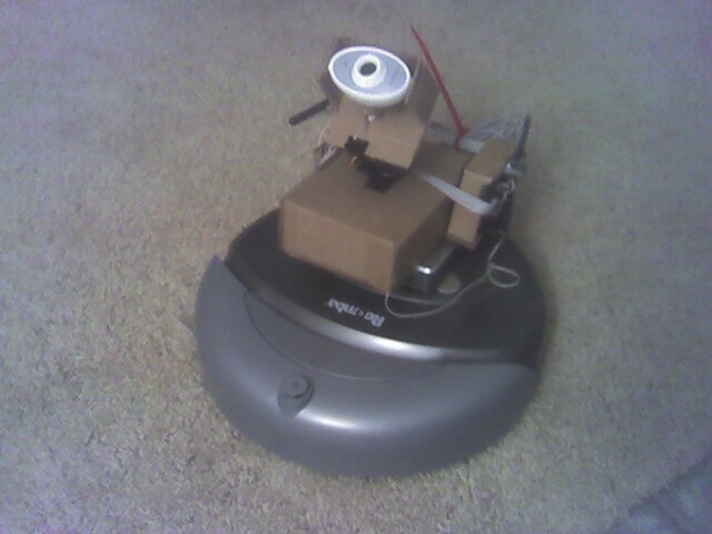
Sparky: Fully Operational